Dynamic impact / Deformable–deformable contact
Tube-to-tube impact
Two steel tubes meet head-on at 15 m/s each. Compare how free motion and axial guidance change the folding pattern under the same initial kinetic energy.
Top: free tubes. Bottom: guided sleds. Guidance is represented by motion constraints on the rear 40 mm of each tube. Both panels use the same fixed camera, mesh-edge display and color scale. The full models are shown as computed.
Free tubes develop a lateral offset and a bent folding pattern. With the rear sleds guided axially, the folds remain more aligned with the impact axis. This comparison shows the effect of the boundary condition on the computed response.
Model and contact
Two deformable steel tubes
Each tube is 50 × 50 × 300 mm with an initial wall thickness of 1.5 mm. The combined model contains 20,000 shell elements and 20,082 nodes. Both versions use the same geometry, mesh and material settings.
Tube contact and folding
Contact acts between the two deformable tubes and between folding regions of each tube. The rear 40 mm of each tube represents an elastic mass-carrying sled section. In the guided version, those nodes move only along the impact axis; their transverse translations and all rotations are restrained.
The tubes start at opposite axial velocities of ±15 m/s. Results are shown from 0 to 20 ms with 161 saved states, computed in single precision on an NVIDIA RTX 4060. The mesh is fixed in these runs.
Final response at 20 ms
| Quantity | Free tubes | Guided sleds |
|---|---|---|
| Axial shortening · Tube A / B | 108.5 / 114.1 mm | 134.8 / 115.3 mm |
| Summed axial shortening | 222.6 mm | 250.1 mm |
| Maximum effective plastic strain (upper/lower fibres) | 1.50 | 1.86 |
| Remaining translational kinetic energy | 8.8 J | 6.1 J |
How shortening is measured: the initial 300 mm length minus each tube’s current extent along the original impact axis, including its rear mass section. Rotation and lateral bending affect this measure in the free case; it is not a direct measure of the material length consumed by folds.
Remaining translational kinetic energy is calculated from the saved nodal masses and velocities. These values alone do not determine how energy is divided among plastic deformation, elastic strain and other contributions.
Inspect the folding pattern
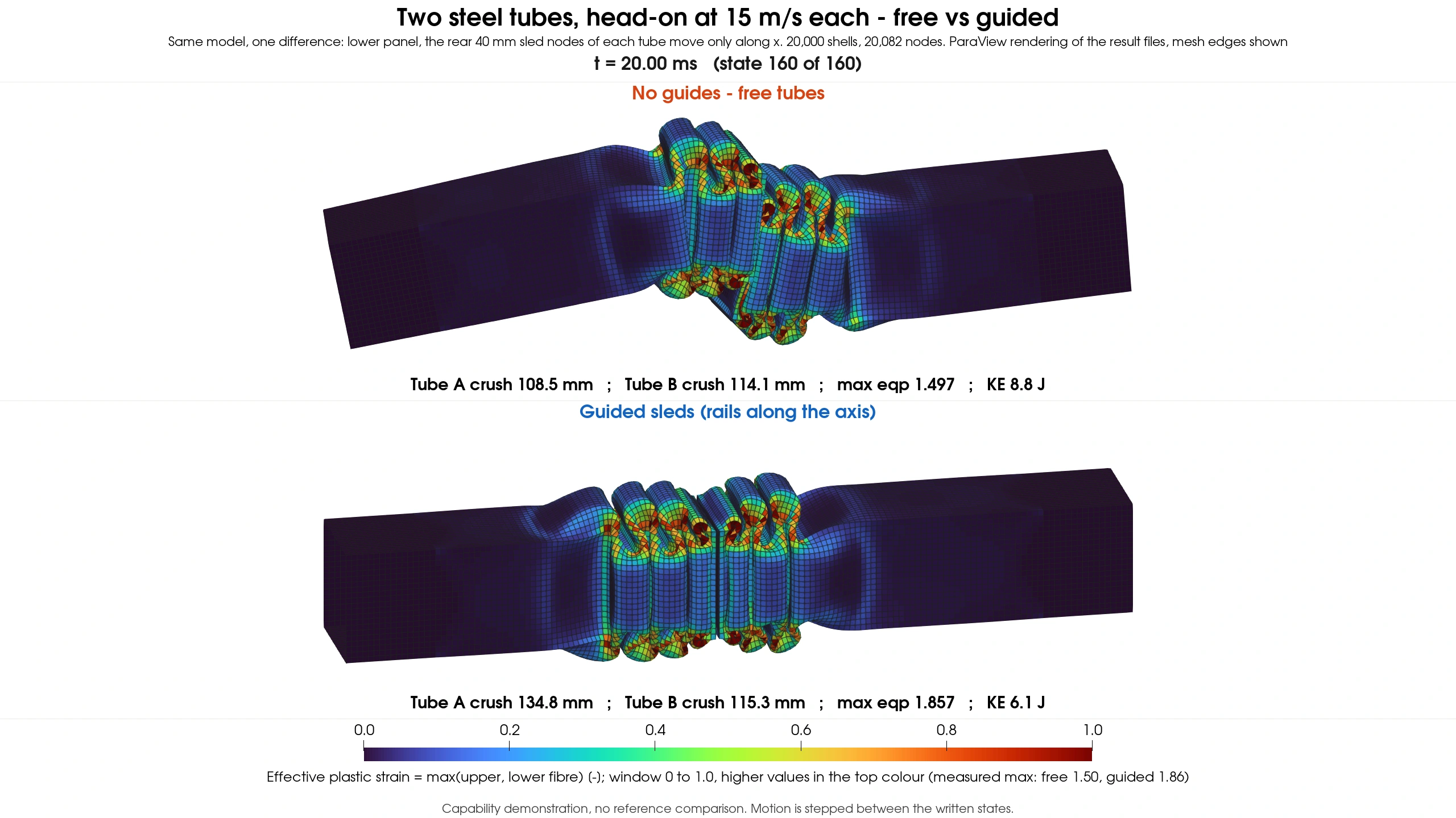
Color is the larger of the upper- and lower-fibre effective plastic strains for each shell. The fixed color window is 0–1.0; values above 1.0 use the top color. The reported strain maxima retain their actual values.
Scope of this example
This is a configured capability demonstration of shell plasticity, deformable–deformable contact and self-contact. It compares two boundary conditions. The figures are run readouts, without an independent experimental or analytical accuracy reference. Playback shows the saved states without interpolating additional simulation results.
SUPPORTED · Configured contact demonstration. Separate numerical comparisons are available in Accuracy.