Elastic half-space reference
Rounded flat-punch contact
Five solid-element configurations compare a rigid rounded punch pressing an elastic block against an axisymmetric half-space reference. The force–indentation curves use contact-force-weighted, profile-corrected approach.
Understand the analysis
A rounded edge around a flat face.
A rigid punch presses into a quarter model of an elastic block. Comparing five solid-element configurations shows how their recorded normal force relates to the same elastic half-space reference.
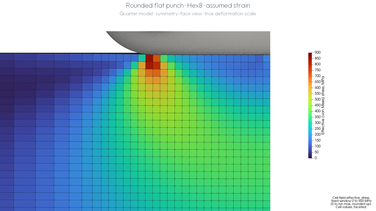
Final saved state of the Hex8 · assumed strain comparison run. The block continues beyond this close-up.
Full size ↗Full loading and hold sequence from the same Hex8 · assumed strain run, shown at true deformation scale.
Open video ↗Color shows block von Mises stress with the original 0–900 MPa legend. It is not contact pressure. The numerical comparison below uses loading states; the video also includes the hold.
Two Hex8, two Tet4 and one Wedge6 configuration are compared using contact-force-weighted, profile-corrected approach. The force curves show the sampled loading range. The bars summarize the mean signed difference for each configuration, with sample counts and ranges in the table.
Force across the loading range.
Download loading data ↓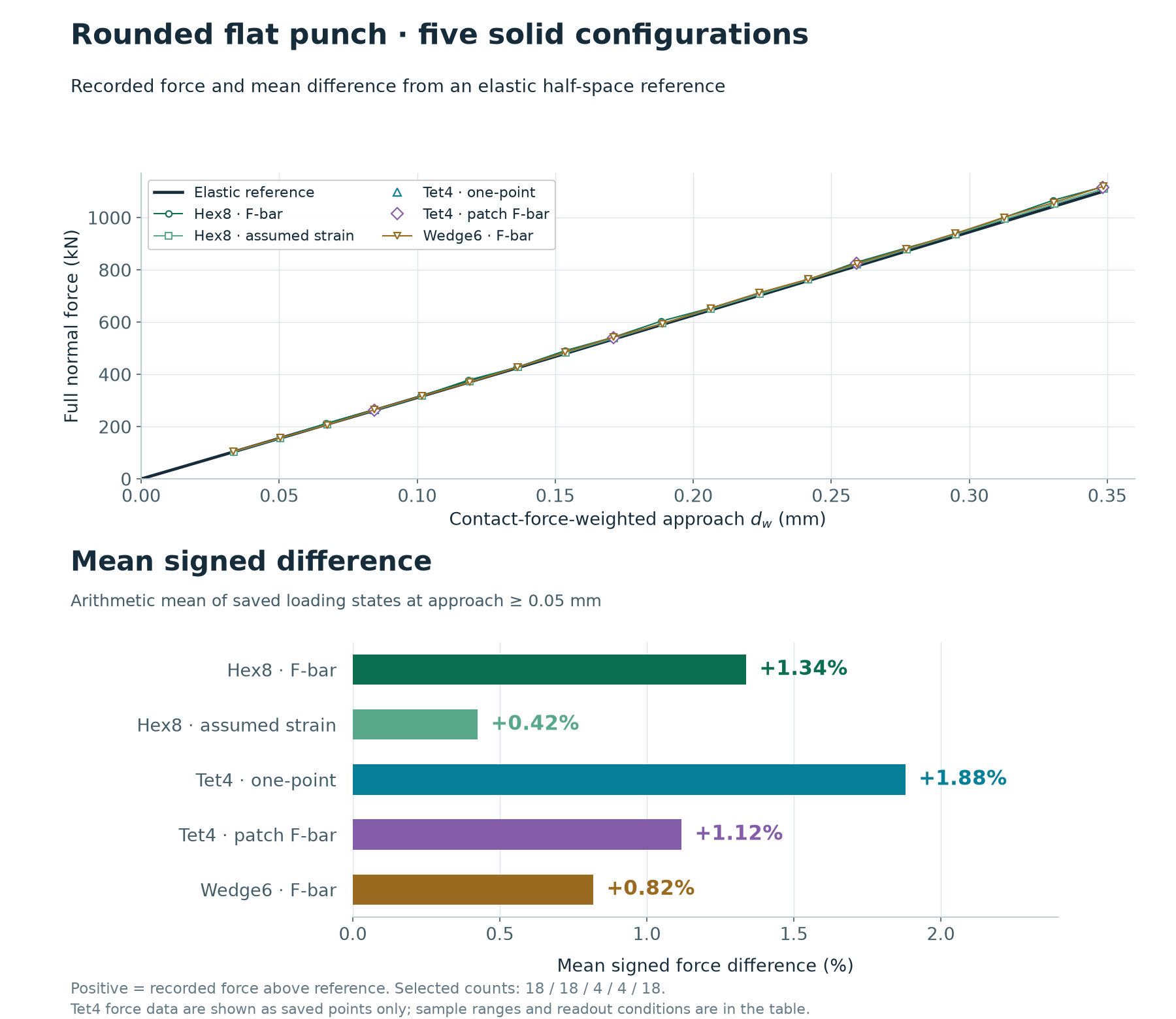
Five solid-element configurations
The table selects saved loading states with contact-force-weighted, profile-corrected approach dw ≥ 0.05 mm. Signed difference is 100 × (recorded full force / reference force at dw − 1); positive means a larger recorded force.
These are arithmetic means over unequal sample counts and different approach ranges. They are not time averages or bounds over every calculation increment. The force curves and loading-data download contain 65 saved loading states with valid reference values; three earlier nonzero states without a supplied reference value are omitted. The bars and table summarize 62 selected states at the stated threshold.
Swipe sideways to read the full table →
| Configuration | Solid elements | Selected states | Actual dw range (mm) | Mean signed difference | Min to max |
|---|---|---|---|---|---|
| Hex8 · F-bar | 438,976 | 18 | 0.0501–0.3486 | +1.34% | −0.27% to +2.37% |
| Hex8 · assumed strain | 438,976 | 18 | 0.0505–0.3488 | +0.42% | −0.32% to +0.88% |
| Tet4 · one-point | 2,633,856 | 4 | 0.0844–0.3481 | +1.88% | +1.28% to +2.12% |
| Tet4 · patch F-bar | 2,633,856 | 4 | 0.0845–0.3485 | +1.12% | +0.54% to +1.46% |
| Wedge6 · F-bar | 877,952 | 18 | 0.0504–0.3486 | +0.82% | −1.45% to +1.74% |
Corrected approach readout
At each loaded surface node, the downward surface displacement is added to the punch’s radial profile height. These local values are averaged with approximate reconstructed contact-force weights to obtain dw. The earlier readout omitted the profile-height contribution around the rounded edge; the force curves, mean bars and table now include it. This corrects the approach coordinate used to evaluate the reference force.
The plotted full force is four times the saved quarter-model reaction, interpolated to the saved displacement states. Reconstructed force totals exceed the recorded reaction by approximately 0.5–0.9%, so the approach weighting is approximate. The plotted force remains the saved reaction. This readout differs from prescribed tool travel and center-node displacement.
Model and comparison conditions
Geometry and material
The punch has a 20 mm flat-face radius and a 10 mm circular corner radius. The quarter block spans 1,600 × 1,600 × 1,600 mm, with symmetry conditions on two faces and a fixed bottom. The elastic material uses E = 70,000 MPa and ν = 0.30. The graded solid mesh has 1.25 mm cells near contact and expands away from it.
Contact and loading
Frictionless penalty contact transfers the prescribed vertical punch motion. From an initial 0.05 mm gap, the tool travels 0.37 mm over 5 ms of simulated loading and is held until 6.25 ms. All five results use FP32. Both Hex8 configurations and Tet4 · one-point use an NVIDIA GeForce RTX 4060; Tet4 · patch F-bar and Wedge6 · F-bar use an NVIDIA L40.
Reference and scope
The reference uses Sneddon’s axisymmetric elastic half-space relations, numerically evaluated for the circular-corner profile. The general relations are also explained in Normal Contact Without Adhesion, Section 2.3. The present circular profile is not the parabolic rounded-edge approximation discussed elsewhere in that chapter.
The reference is static and assumes an elastic half-space. The numerical model has finite boundaries, faceted tooling, penalty contact and explicit loading. No mesh-convergence, loading-rate or quasi-static energy study is established by this comparison. Choosing a different indentation readout, such as center-node displacement, changes the force differences and can place them outside the table’s range. The force comparison does not validate contact area, pressure or the displayed local stress field.
Relation to the published study
The earlier published solid-element study reported a +1.69% force comparison for a different coarse Tet4 model with a 100 × 100 × 60 mm block. Its model and readout differ from the current comparison. That percentage is historical evidence for the earlier study and is not a result in the five-configuration table above.
These are evaluation results recorded on 8 October 2026. They describe the supplied configurations and do not establish identical behavior across devices or every released solver version.
SUPPORTED · Numerical force comparison for the stated configurations and readout. Evidence and comparison scope ↗